
Ashley Rosen
This past summer, I had the incredible opportunity to work as a conservation engineering intern at the World Wildlife Fund.
One of my main projects was making some improvements to a thermal camera system WWF uses internationally. The system consists of a FLIR thermal camera with a protective casing and mount that was designed by WWF Conservation Engineer, Eric Becker. The camera system can be seen at the top of the ranger's car in the image below.
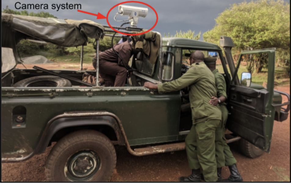
Currently, two of these cameras are used in a protected area in Kenya to look for poachers at night. As the sun sets, at least three teams of rangers will set out on patrol. One team of rangers will have the camera with them and drive to a high-risk area where they will park until morning. After parking, the team will attach the camera to their vehicles and scan for threats. If the rangers see a potential threat, they use their radios to alert and direct the other ranger teams to apprehend the poacher. After the patrol, the rangers remove the camera from their vehicle and store it in a weather-proof case. The use of just these two cameras has already resulted in 300 arrests.
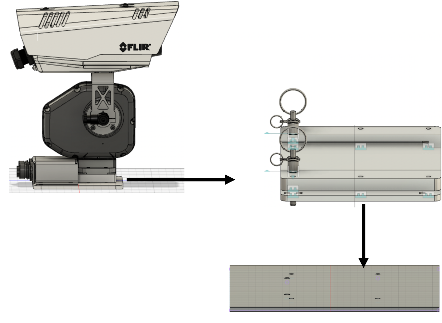
This camera system has 3 main parts: the camera and the plate it’s attached to (shown on the top left of the above image), the plate it slides into (shown on the top right), and the plate that is welded to the rangers’ vehicles (shown on the bottom right). The plate that the camera slides into is permanently attached to the plate beneath it, which is welded to the vehicle. The only part that gets removed is the camera, which rangers attach and remove from their vehicles multiple times a night (in complete darkness), as rangers cannot drive with the camera attached. This current design has a sticking problem when the camera assembly on the left slides into the plate on the right, caused by a buildup of dirt and dust inside the assembly.
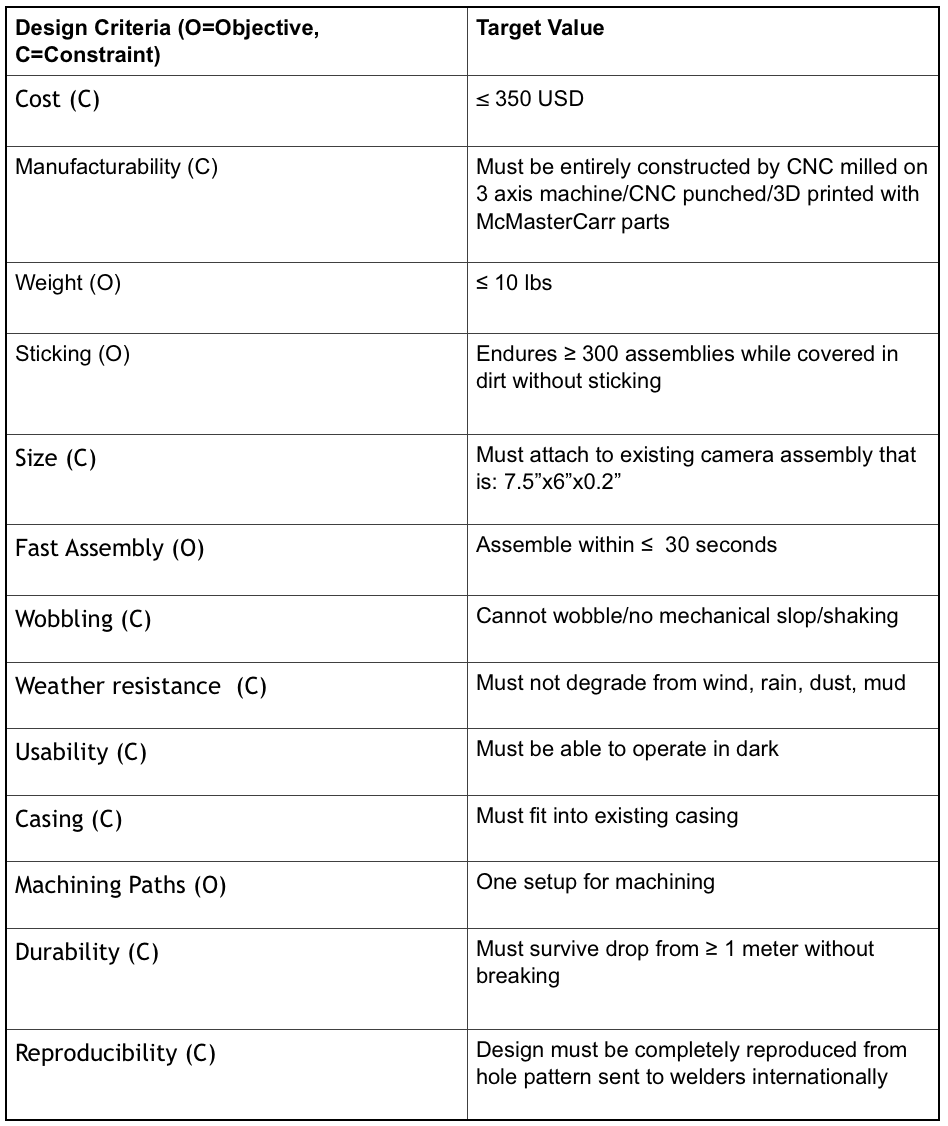
To address this sticking issue, I did research in 2 main areas: how materials attach to each other and low friction materials. I looked at camera sliders, legos, rack and pinion systems, and linear slides. To better understand low-friction materials, I read about the properties of PTFE (used to make the Teflon non-stick coating on pans), Acetal, and other plastics. After doing this research, I created my design criteria, which were standards the design had to meet. The target values in the table below for the objectives were goals for the design, and the target values for the constraints were minimum requirements.
After I made the design criteria, I then brainstormed! I generated 22 ideas on how to connect the camera to the rangers' cars. The ideas ranged from adding cutouts or slots to adding buckles like you see on a backpack. This project was particularly interesting, as the design solution had to address the sticking problem but also be put together easily and quickly in the dark.
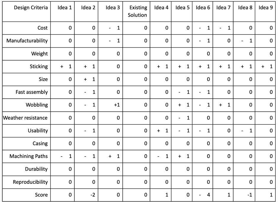
I refined the ideas through Pugh Screening matrices, one of which is shown below. A Pugh Screening Matrix compares the new ideas to the existing solution to determine which best meet the design criteria. Designs that meet a criteria better than the existing solution are scored with a +1, designs that do not meet the criteria as well are scored with a -1, and designs that meet the criteria just as well as the existing solution are scored with a 0.
One of the designs with the highest scores was Idea 9. The main concept behind this idea was to make as much as possible out of low-friction plastic. This design was selected because it was the only design that did not require any modifications (ie adding slots or drilling additional holes) to be made to the camera plate.
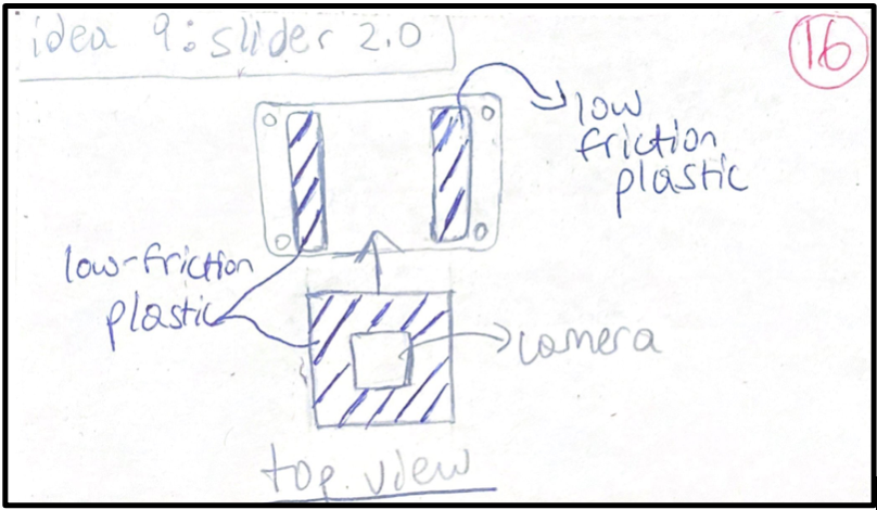
To keep the camera plate part of the design the same but still apply the concept behind Idea 9, the rails that the camera slides into became plastic, while the camera plate remained metal. To further reduce friction, cutouts were added to the rails.
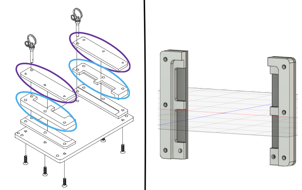
What I contributed to the design can be seen above on the left side of the image. I created cutouts in the existing rails to make the rails circled in blue and added the protective cover plates, which are circled in purple. The right side of the picture is a CAD drawing of the new rails (light gray) and the metal protective cover plates (dark gray).
The CAD designs were created using Autodesk Fusion 360, which is a free software available for both Mac and PC. Using the Manufacture function of Fusion 360, I was able to add tool paths, showing how the raw materials should be cut to result in the parts shown above.
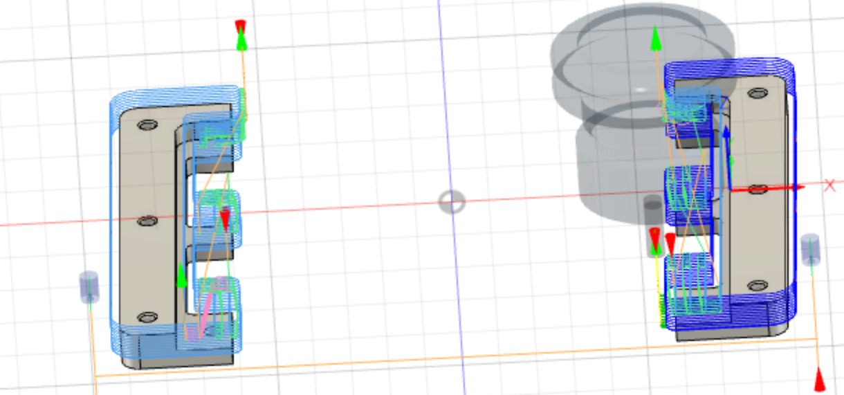
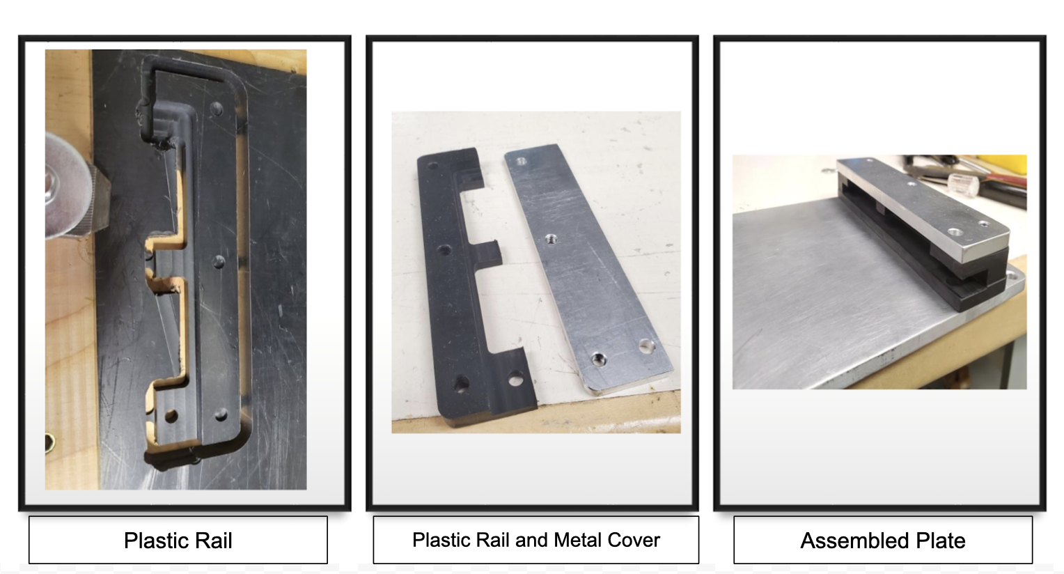
Eric was able to use the CAD designs and tool paths to machine the parts, which are shown below.
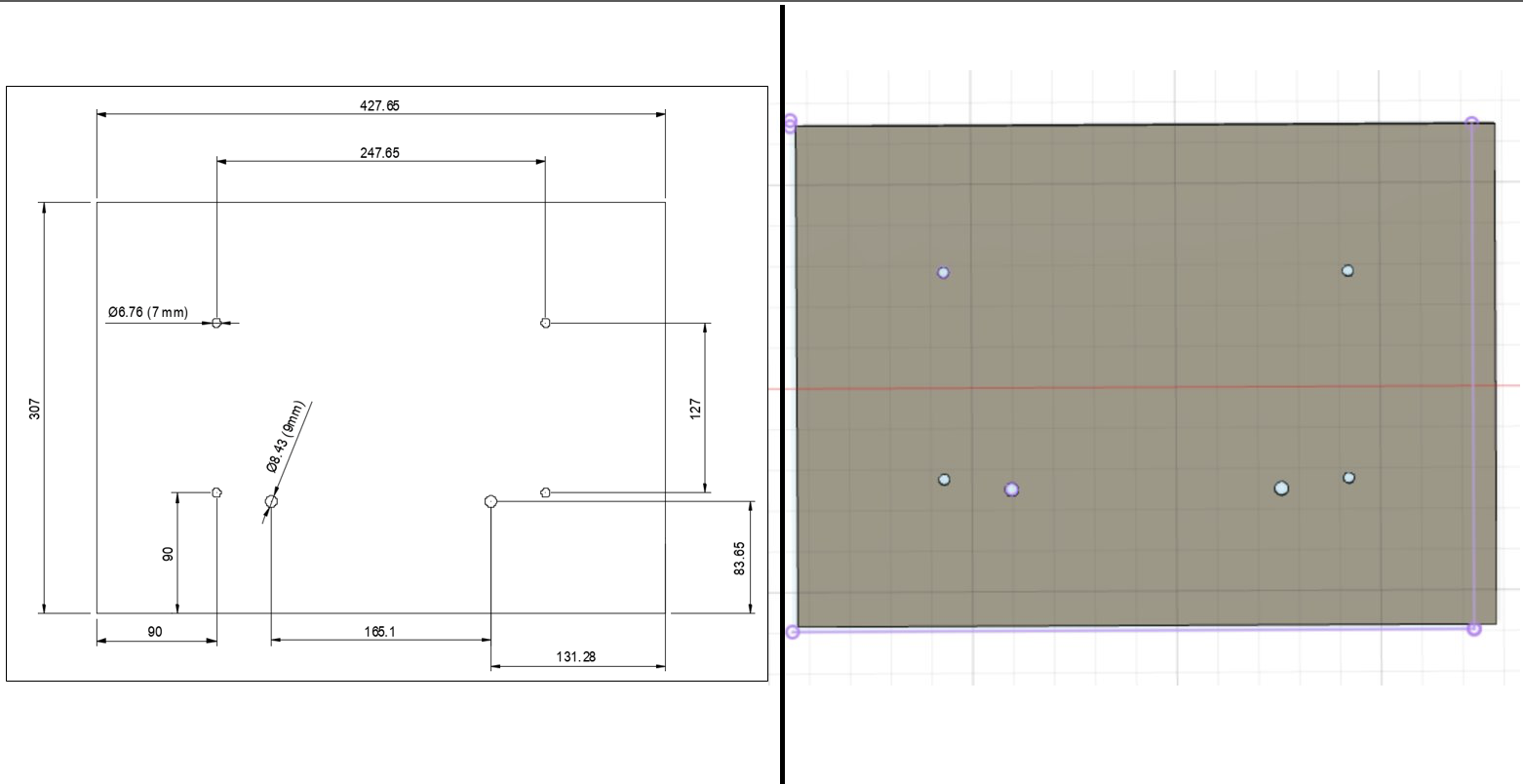
Additionally, I created a hole pattern of the plate that the rangers will weld to their vehicles.
The hole pattern on the left side of the above picture shows how the plate should be cut and where the holes should be drilled. It also shows what size drill bit should be used to make the holes. A CAD model of what a plate made using the hole pattern would look like is on the right.
The next steps for this project are to assemble and test a prototype of the newest design. The camera mount system will then be finalized, and 15 of the new camera systems will be sent to 8 protected areas across Kenya this Fall.
Add the first post in this thread.